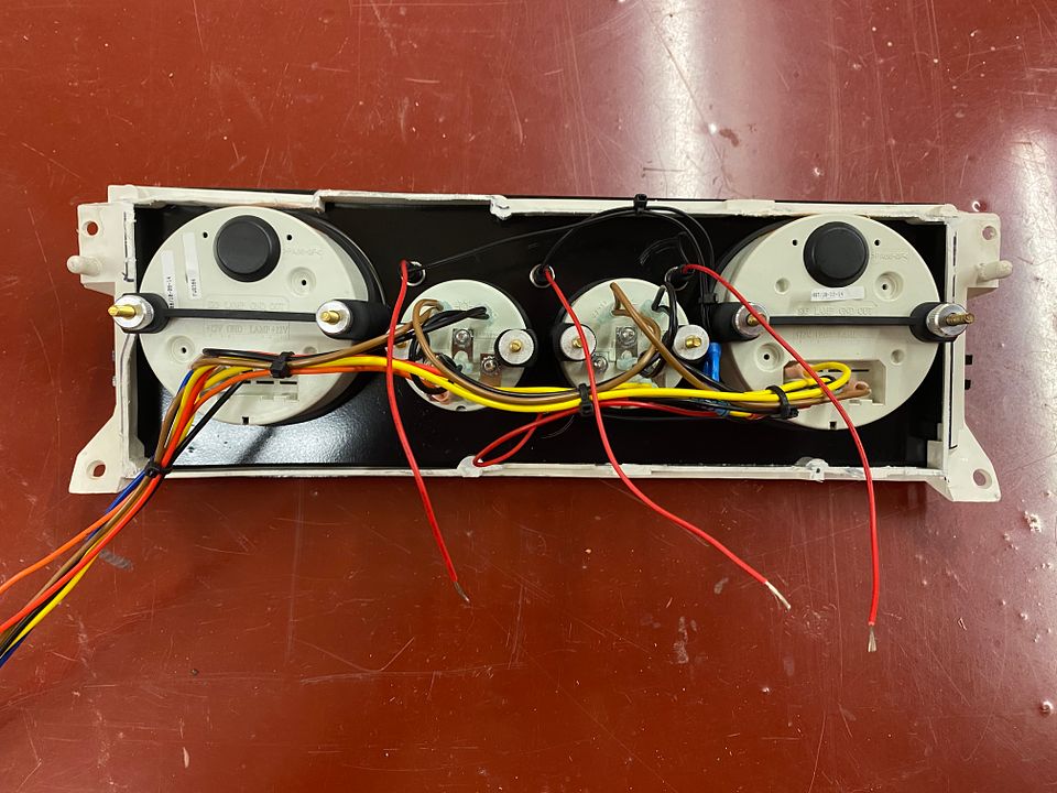
Wired up and left long leads to tap the factory dash wires. Left the VSS signal wire off the speedo 12’ long so it will reach the transmission. No more speedo cable for this car. Will take the speedo cable apart, clean and lube to hold it back as a spare for the Coupe being Ford no longer makes them.
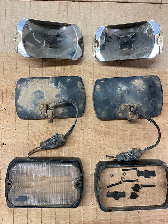
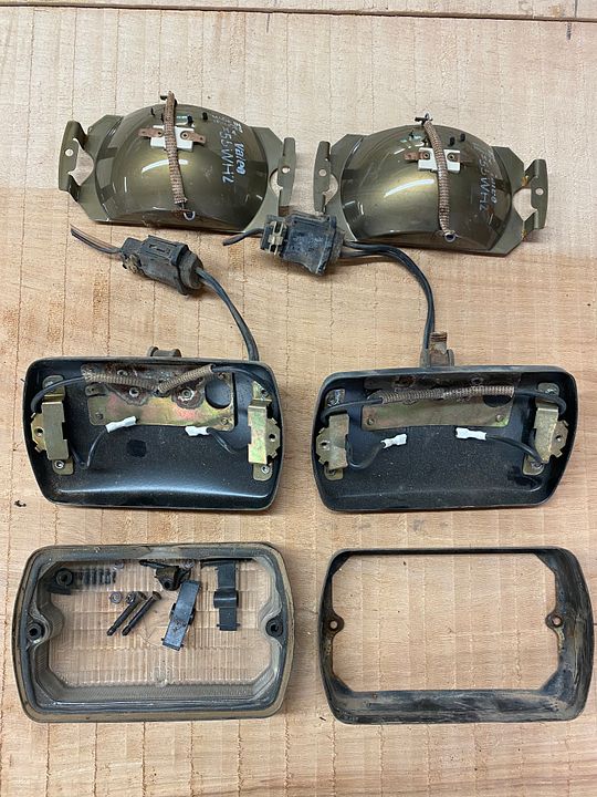
I have this left over from making one set for my car so put both together and you would have a complete set. I would take $50 shipped to any of the lower 48 states.
I inquired as we have a lot of shops here in the Tulsa area that cater to the airline industry. They were guessing around $700 so I figured doing it by hand and understanding it would not be perfect was worth a shot. What I was thinking initially was the two pieces (white instrument housing, and the black trim ring) would have to be scanned into a model, the model changed to fit the gauges, and then the two pieces printed is what I was thinking. Now after doing what I have done I would probably just have the black trim ring scanned, model modified to fit the gauges, and then printed. Maybe someday down the road as I still have my factory instrument cluster and can use the black trim ring out of that to scan.
So I am not showing the metal plate painted all by itself as it looked like . Had debris in it the first time and it alligator skinned on me (not dry enough or at least that is what I chalked it up to) which would be due to me not being patient and wanting to see it all together. I took my time yesterday and wet sanded the plate down and hung it outside in the high heat, wiped it down with some brake cleaner, and then hung it in the shop as it was a lot lower in humidity due to the dehumidifier and window unit running full tilt. Shot it and it laid down so I left it there to hang for the week. The black trim piece came out pretty good and the paint laid down good so its hanging this week as well.
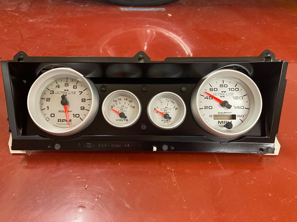
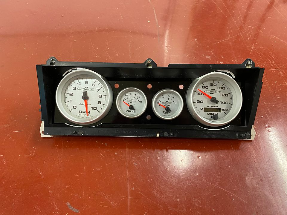
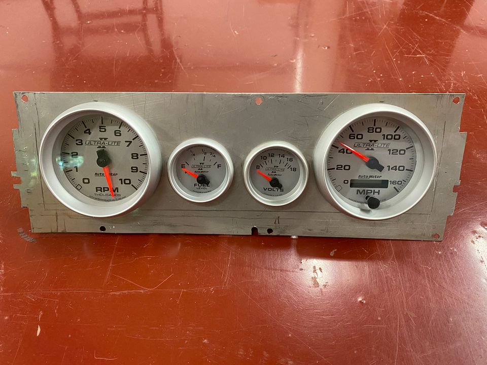
So this is the picture I took of the cluster with the metal plate on its first paint job, gauges installed and the trim piece worked so you can see all of the gauge trim ring. Rough but you get the idea.
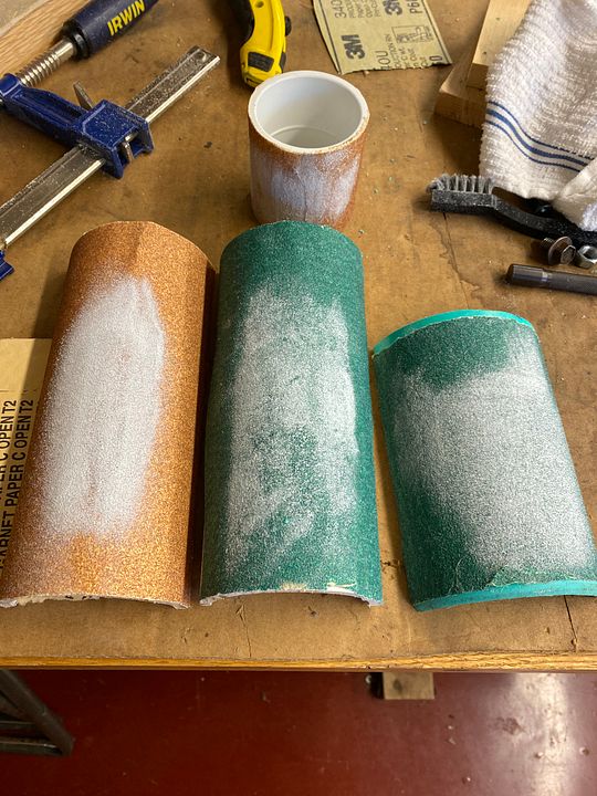
Spent some additional time shaping the reliefs on the black trim piece which was a bit of a pain as I am limited on body working tools so had to improvise. I used a 2" PVC coupler, 3" PVC, and 4" PVC with sand paper spray glued to them to remove material from the trim piece.
This is the metal plate hanging after the brake cleaner wipe down:
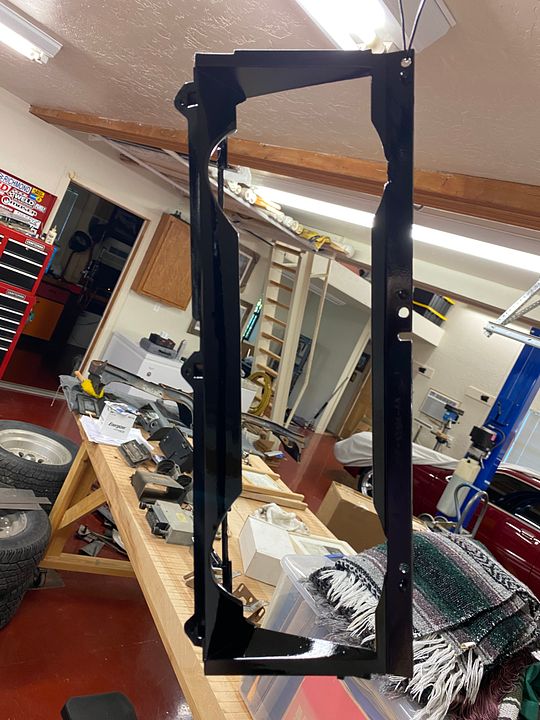
And this is the trim piece handing after being shot:
Should get back on it this coming weekend and get it all put together and wired up at a minimum. If things go well dash will come out of the car and it will go in.
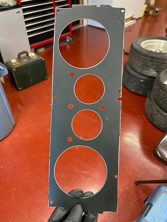
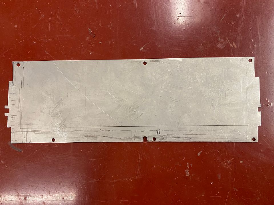
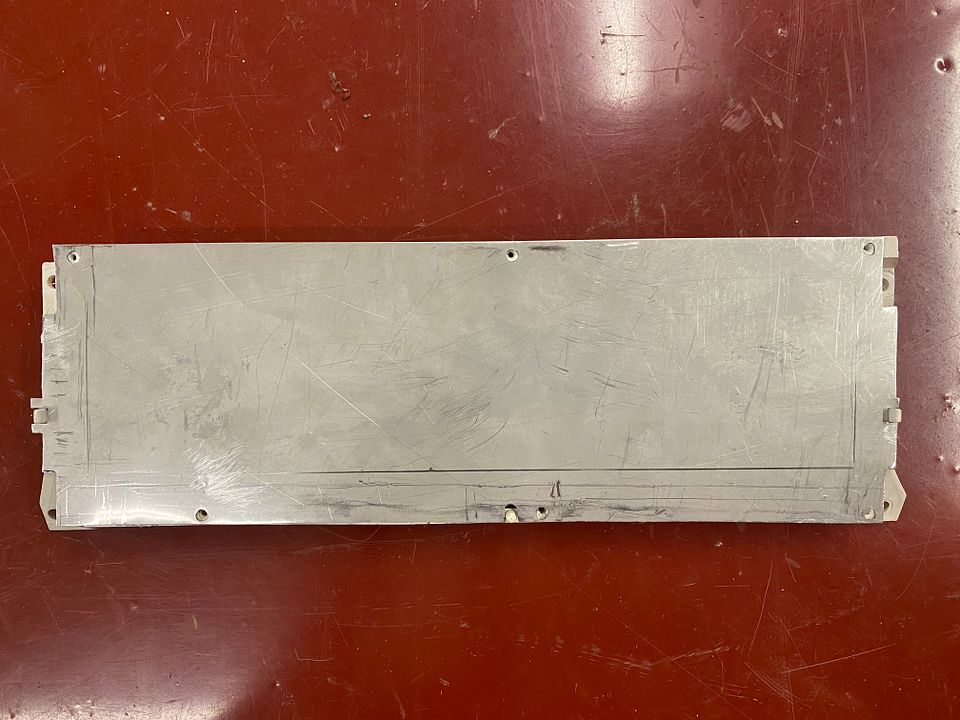
So made some progress the last couple of days. Traced the black trim panel onto a s of 18 ga metal and got that cut out.
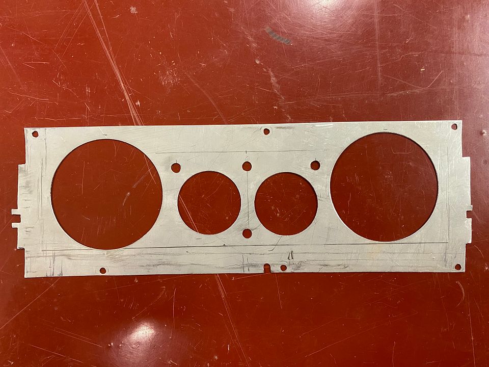
Metal cut to fit:
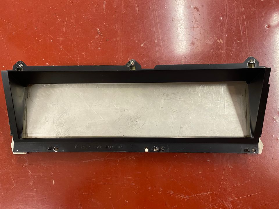
Metal Mocked up on the white instrument panel:
With the black trim over the metal:
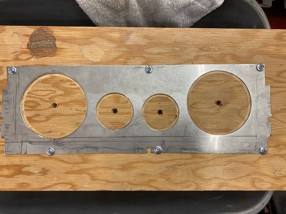
Panel screwed to plywood with the gauge holes cut out via bimetal hole saws and the drill press:
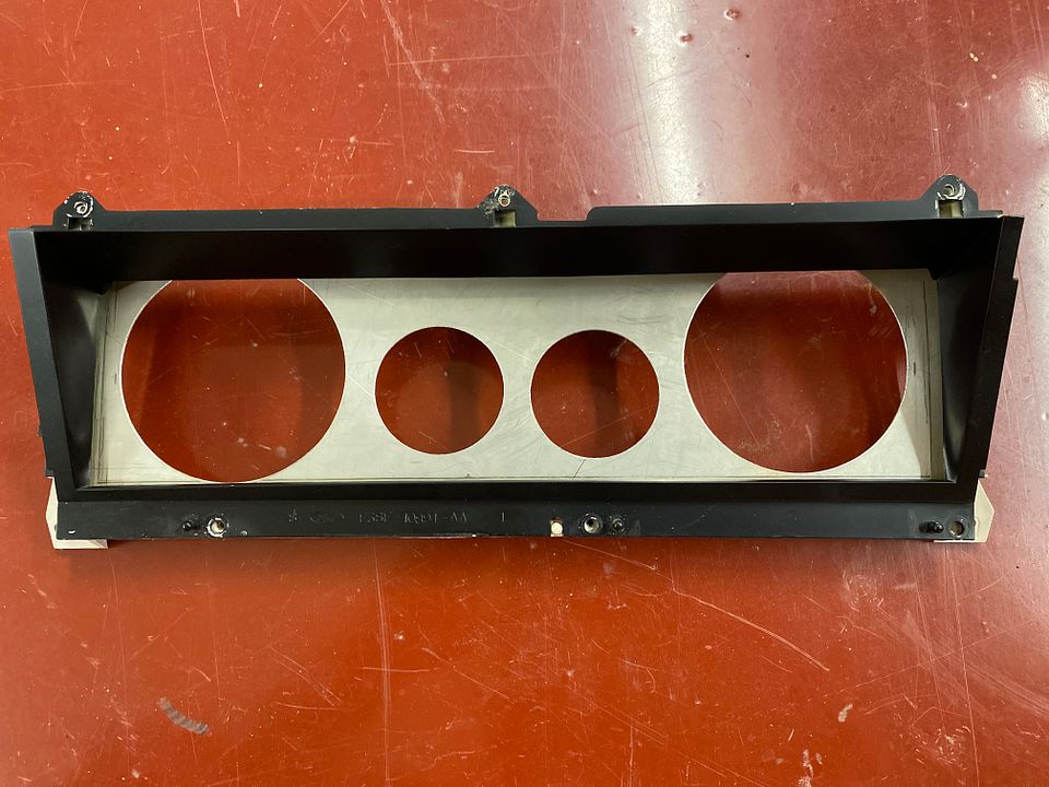
Back together and you can see where I am going to have to relieve the trim piece at the top:
I’m thinking a short piece of 3” PVC pipe split length wise in half with some sandpaper glued to it. Have the pipe and sand paper but no spray glue so about to head to Lowes.
Here are the gauges popped in the holes:
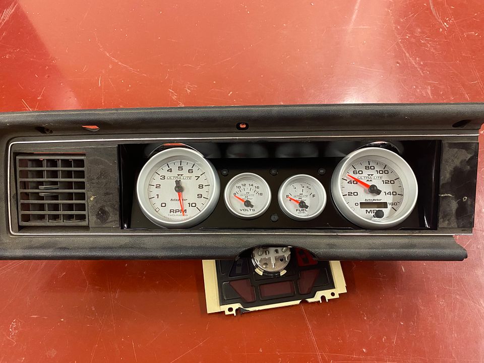
Will post up some pics after I get the reliefs done and the panel painted.
I know this is super old but are you referring to the remote turn on led voltage from the head unit to the amp? I know for sure that the 1994 and up Mustangs have 5V+ for the remote amp turn on.
I am going to work on the 18 ga flat piece this weekend and if all goes well will have the gauges mocked up and if I like it I will drill the holes for the indicator lights and get it painted.
So it was more me wanting all of the indicator light assemblies to be the same and they do not make an incandescent one. These are Taiss units off Amazon that I will be using:
Ordered the diode and resistor but had to get five each so guess I have extras.
I am pretty sure this has been covered but I wanted to bring this up in case anyone else goes down this road. It is not that you do not want to use an LED for the battery indicator light in the dash you just have to understand its function to use an LED.
It is my understanding (will defer to anyone else that has a better explanation) that our cars have an incandescent light bulb (paralleled by a resistor in the printed circuit board) for the battery indicator lamp. The bulb is inline between the ignition switch and the regulator for the alternator. As long as the voltage from the battery is lower than what the alternator is putting out the battery indicator light will illuminate. Once the alternator is generating more voltage than the battery then the light will go out. This makes sense being the light comes on when the ignition is switched to on and the engine is not running the battery indicator light illuminates. When the engine is running and the alternator is making more voltage (typically higher than 12.7 volts) than the battery is putting out the light goes out.
The reason for the resistor installed parallel to the battery indicator lamp is in case the lamp fails the resistor will keep the alternator charging and not leave you stranded. So if your lamp is burned out and the car is not charging don't forget about the resistor if you have exhausted the usual suspects (bad alternator or blown fusible links) and before you start chasing a wiring issue.
The reason for the incandescent light is the resistance of the bulb (2 watts or 160 mA at 12V) is needed to trigger the transistor (which I believer are in the voltage regulator and take about 60 mA to trigger) into conducting which then results in the alternator producing a voltage higher than the battery which turns the battery illumination light out. Prior to the transistor triggering the alternator to charge it sinks current through the lamp and gives a path to ground hence the lamp illuminating. That took me some time to digest and googling some terms to I could wrap my brain around that.
So basically the incandescent light is needed to trigger the alternator to start charging and then when the voltage out of the alternator is higher than the static battery voltage the transistor is no longer sinking the lamp to ground and the light goes out.
The use of an LED by itself (resistance is 20-30 mA) for the battery indicator will not generate enough resistance to create the needed amperage to get the alternator to charge. You can make it work with a diode wired in series but upstream of the LED and a resistor wired in parallel with the LED. The way I understand it is the diode is there to keep the battery from going dead by back feeding to a ground. I think it would have to sit a loooong time but its possible.
I found this wiring diagram that shows how to go about wiring what I have described above:
I am going to use an LED and wire it just like this and with the same values on the diode and resistor. Hopefully this works as I am using LED's on the turn signals and hi beam indicators. Again, if I have misspoke or provided false information please correct me as this is not my area of expertise by any means. I am pretty good at 12V stuff (alarm and car audio back ground) but by no means an expert.

.jpg?width=590&height=370&fit=bounds)
.jpg?width=590&height=370&fit=bounds)
.jpg?width=590&height=370&fit=bounds)
